Computer-aided design (CAD) software has revolutionized the way engineers and designers create everything from consumer products to large-scale manufacturing equipment. As a PLM developer, understanding the landscape of mechanical and electrical CAD tools can help you build software that integrates with and enhances these systems. This guide provides an overview of the key capabilities, file formats, and programming interfaces available in modern CAD platforms.
Mechanical CAD
Mechanical CAD programs allow users to model and analyze physical components and assemblies. Key features include:
Solid and surface modeling:
Solid modeling is creating a 3D object by adding and subtracting simple shapes to form a solid structure. Imagine you want to design a car. You might begin with a rectangular block to represent the main body. Then, you add cylinders for the wheels and maybe a sphere for the driver’s compartment. As you add and subtract these shapes, the software keeps track of the volume, ensuring your car is a solid object. The resulting B-rep (boundary representation) solid models contain complete topological information to represent the modeled geometry.
Surface modeling, on the other hand, is like wrapping the solid object in a virtual skin. It focuses on defining the external surfaces of an object. So, you might use surface modeling to round the edges of the car, create a smooth roof, and shape the hood. While the inside of the car remains a solid (thanks to solid modeling), surface modeling helps make it visually appealing.
Both solid and surface modeling can be combined to build up complex shapes. CAD kernels like ACIS and Parasolid provide the underlying modeling engines.
Assembly modeling:
Assembling individual 3D components into an overall product structure is a core CAD function. Positioning components precisely is enabled through mate connectors like axis align, tangent, concentric, parallel, and others. Advanced mates include cam, path, and gear connections.

Imagine you’ve created individual 3D models for the various parts of your car using solid and surface modeling. You have the main body, the wheels, the driver’s compartment, and maybe even some accessories like headlights and a spoiler. Assembly modeling involves bringing all these separate components together, precisely positioned through various mate connectors, to form the complete car. Assemblies can be structured hierarchically, with subassemblies nested as needed.
PLM data management capabilities track all these components, sub-assemblies, part configurations, substitute components, and generate bills of materials.
Drafting:
While 3D modeling defines the physical design, 2D drawings remain vital for manufacturing and service. CAD systems automate drafting by generating views, sections, details, and projections from 3D models. Dimensions, tolerances, notes, parts lists, and other annotations are applied automatically based on standards or user-defined rules. Drawings update as the 3D model changes. Templates streamline generating deliverables by applying company title blocks, border, text styles, and other elements consistently. PLM manages these drawings that are output electronically in PDF or raster formats for digital distribution.
Rendering:

Realistic visualization is crucial for design review, marketing, and user manuals. Rendering engines apply materials, lighting, reflections, and environment maps to CAD models to simulate real-world appearance. Materials define properties including color, texture, reflectivity, and roughness. Component appearances can be saved and reused. Light types include spot, point, directional with control over color, intensity, and other parameters. Renderers use raytracing, radiosity, and other computational techniques to achieve photorealistic results. Some PLM platforms offer real-time rendering for interactive visualizations while others manage the revisions of the rendered images.
Simulation :
Verifying the physical performance of designs is vital to avoiding costly prototyping iterations. Finite Element Analysis (FEA) tools allow engineers to simulate structural, vibration, thermal, fluid flow, and other behaviors. Users define operating loads and constraints on the CAD model. Meshing divides the geometry into finite elements for computation. Results show stresses, displacements, velocities, temperatures and more. PLM platforms capture the simulation results as the designs are iterated allowing to optimize the digital prototype prior to manufacture.
CAM and toolpath generation:
To prepare CAD models for downstream manufacturing, platforms provide computer-aided manufacturing capabilities. For CNC machining, CAM modules convert designs into machining operations like facing, contouring, pocketing, drilling, and threading. The system automatically generates toolpaths optimized for the selected tools and stock geometries. Similar functionality outputs toolpaths for 3D printing or programming robot welders. PLM platforms help manage these CAM files directly from the CAD tools.
Leading mechanical CAD packages include SolidWorks, Creo, Inventor, CATIA, and NX. Interoperability is enabled through standard file formats like STEP, IGES, and Parasolid.
Electrical CAD
Electrical CAD software provides tools for designing schematics, PCB layouts, wiring diagrams, and panel designs. Main features are:
Schematic capture:

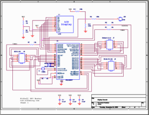
Schematics provide the logical representation of electrical circuits using abstract symbols to represent components like resistors, capacitors, integrated circuits, and connectors. Libraries contain symbols for common parts which can be dragged onto the design canvas. Wiring tools connect the pins and terminals with net connections automatically named for circuit node identification. Schematics are the source document for PCB layout and wiring design.
Features like design reuse, variant management, and parametric components boost productivity. Electrical rules checking verifies correctness. The schematic editor integrates with simulation for functional validation of circuit operation early in the flow.
PCB layout:
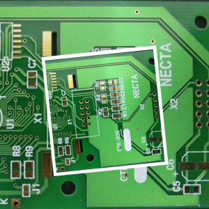
 Laying out a printed circuit board (PCB) transforms the logical schematic into the physical implementation. The layout defines component footprints, routing, layer stackup, finished dimensions, etc. Wizards assist with placing parts while interactive routing modes allow efficient trace wiring. Design rule checking validates the PCB against electrical, manufacturing, and assembly constraints. Powerful visualization, such as transparency and x-ray, simplifies working with complex multilayer boards. Integration with MCAD allows inserting PCBs into mechanical enclosures and wire routing.
When complete, output generation produces Gerber, drill, and assembly files needed for fabrication and assembly, which are managed in the PLM.
Wiring design:
For wired electromechanical products, tools simplify routing cables and wire harnesses throughout 3D mechanical assemblies. Harness design defines logical connections between endpoints. Automated routing then determines optimal paths satisfying length, clearance, and other parameters. The system generates drawings detailing the harness fabrication including custom lengths, connectors, splices, labels, and assembly instructions. Interfaces with electrical simulation verify voltage drop, load capacity, and signal performance. Close integration between wiring, PCB layout, and MCAD results in a unified digital prototype.
Panel design:
Control cabinets, operator interfaces, and electronics enclosures require carefully planning the layout of indicators, switches, wire ducts, and components. Panel design tools allow interactive arrangement of elements within 2D or 3D cabinet models. Standards-driven placement rules guide efficient operation and orderly aesthetics. Manufacturing outputs include panel drawings, schematics, BOMs, and assembly instructions. Mockup visualizations provide an interactive preview supporting design review and usability testing. Predefined templates and symbol libraries help accelerate common tasks.
Major electrical CAD platforms include Altium, Cadence, Zuken, and Autodesk EAGLE. Data exchange relies on standards like ODBC, Gerber, and IPC-2581.
Programming CAD
While graphical user interfaces remain the primary method of interacting with CAD software, programming interfaces allow customization, automation, and integration with other engineering systems, including PLM.
API Access:
Most major CAD platforms like SolidWorks, Creo, Inventor, and Autodesk Fusion provide APIs for accessing model data and automating workflows. Languages include C/C++, .NET, Python, and Visual Basic. APIs give programmatic control over the user interface, leverage advanced modeling functionality, and extract design data. Add-ins and plug-ins created with the API can customize and augment CAD workflows through new menus, toolbars, and dialogs. API access is key for tasks like design automation, generative design, model simplification, and engineering change integration.
Journaling:
Journaling records manual interactions with the CAD interface as an editable macro. Scripts capture mouse clicks, keyboard input, command usage, and operations. The journal can be rerun to automate repetitive modeling and documentation tasks. Journaling is an easy way to start automating workflows without programming. However, journals are limited to replicating GUI interactions only.
Visual Basic:
Visual Basic for Applications (VBA) allows embedding macros directly in CAD documents like drawings and assemblies. VBA provides an approachable programming option for designers without coding experience. Macros automate repetitive drawing annotations, run design checks, populate BOMs, and extract data. Security concerns often restrict VBA capabilities to prevent dangerous or malicious actions. VBA interoperability with Office applications helps integrate CAD data workflows.
COM Interop:
The Component Object Model (COM) enables external applications to access CAD models and data programmatically on Windows systems. COM provides language-neutral interfaces for capabilities like rendering, geometry access, visualization, file I/O, and user interface integration. COM is used for integrating simulation, manufacturing, PLM, and enterprise systems with CAD.
CAD Kernels:
Independent CAD modeling kernels provide solid and surface modeling capabilities that can be programmed through C++, .NET, and C APIs. Third party kernels like ACIS, CGM, and Parasolid offer an alternative to proprietary CAD geometry engines. Applications include developing CAD converters, optimizing models, generative design, and custom modeling tools.
CAD Interchange:
Libraries like FreeCAD, NodeCAD, JSCAD, and CADHub simplify working with standard CAD file formats like STEP, IGES, and STL in JavaScript applications. By leveraging these interfaces, developers can build specialized tools for design automation, generative design, model simplification, design optimization, and engineering change management.